Checking fixtures, inspection gauges and custom gauges built to drawing
CAD-IS is a gauge and fixture manufacturer: checking fixtures, inspection and measuring fixtures, CMM fixtures, bend and brazing gauges and custom gauges built to drawing or CAD data – for fluid and line systems, tube bending, sheet metal and series assembly. An inspection report for the gauge is available on request. Since 1999 in Karben near Frankfurt, Germany, ISO 9001:2015.
To drawing or CAD
Built from your drawings or STEP/IGES files. If no documentation exists, we capture the geometry directly from the part.
Design and manufacturing under one roof
3D model, machining and assembly are all done in-house, with one contact from inquiry to ready-to-use gauge.
ISO 9001:2015 certified
Documented quality management system, certified by TÜV Rheinland. Valid until May 2029.
What kinds of gauges does CAD-IS build?
Gauges are dedicated inspection tools that safeguard the dimensional accuracy of parts in series production. Unlike universal measuring instruments, they physically embody the nominal geometry of a specific part, enabling a fast, operator-independent decision right on the line. CAD-IS builds all common gauge types to drawing: as one-offs, in small batches, or as replacements for worn or lost gauges.
Checking fixtures and go/no-go gauges
Checking hole spacing, stop points, positional references and form features. Checking fixtures replace time-consuming individual measurements with a pass/fail decision in seconds and are suited to final inspection as well as in-process checks during production.
Inspection and measuring fixtures
Fixtures that locate a part in a defined position and verify several features in a single inspection cycle – with check pins, go/no-go gauges, dial indicators or sensors. They combine the speed of a gauge with the informative value of a measurement and can be integrated into inspection stations.
CMM fixtures
Fixtures that hold a part repeatably on the coordinate measuring machine or under the measuring arm. They establish the datums unambiguously, shorten measuring time and make measurements comparable across initial sample inspection, production and complaints.
Bend gauges for tubes and lines
Contour-defining gauges for tubes, hoses and profiles. They verify that a bent part conforms to the specified 3D shape and immediately reveal deviations in bend angle, leg length and rotation. Typically used in fluid line systems and tube bending.
Brazing fixtures and assembly jigs
Positioning tools that hold components precisely in place during brazing or assembly and limit thermal distortion. Interchangeable plates allow one base gauge to be reused across part variants, which noticeably reduces tooling costs.
Contour gauges for free-form surfaces
Inspection tooling for dimensionally defined curves, cross-sections and transitions that are difficult to capture with standard measuring instruments. Machined on the 5-axis machining center in a single setup, so there are no re-clamping errors.
Custom gauges to drawing
Every gauge from CAD-IS is a part-specific custom gauge: designed and built for a specific part, its inspection features and its inspection station. Standard catalog gauges such as thread plug gauges, limit plug gauges or ring gauges are not part of our program.
Gauges for tube, hose and fluid line systems
A large share of our gauges is built for bent tube and hose assemblies: coolant, fuel, A/C and hydraulic lines as well as plastic tubing with multiple bends and connectors. We check the 3D shape, connector position, bend angles and hose routing – for a single part often with a complete set of coordinated tooling: bend gauges, straightening fixtures, a checking fixture and an interchangeable plate for final inspection, all designed to the same datum system.
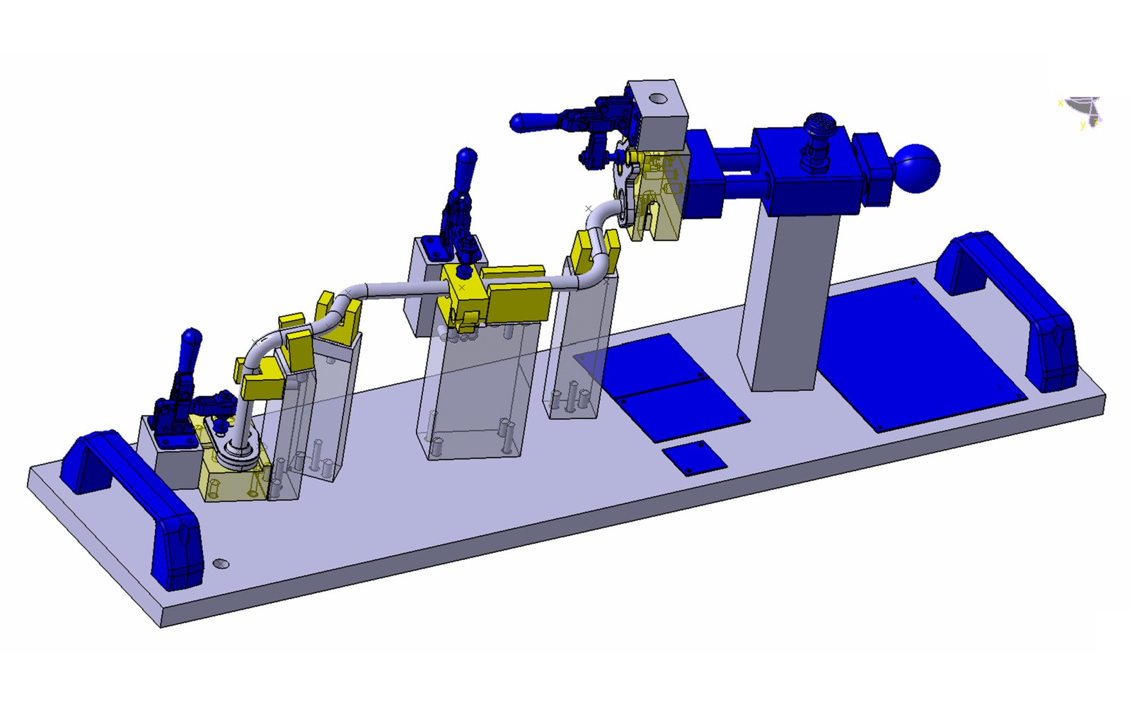
Bend gauge for a tube elbow: locators, stops and clamps on a common base plate.
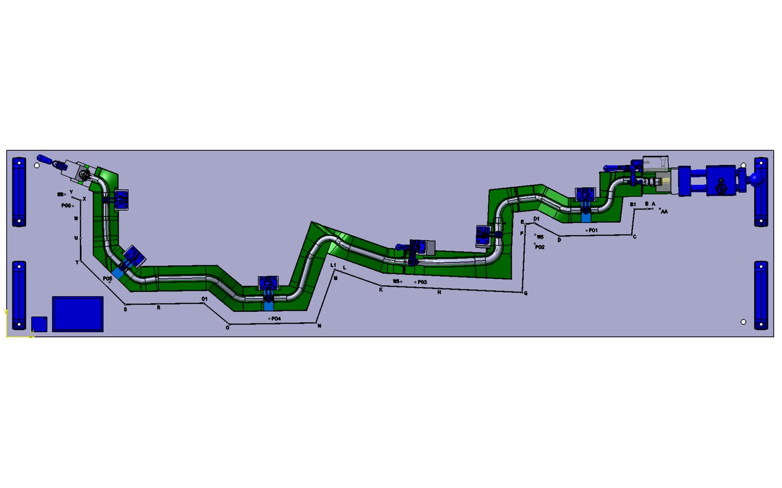
Contour checking fixture for a plastic line: routing, bends and connector position are checked in one operation.
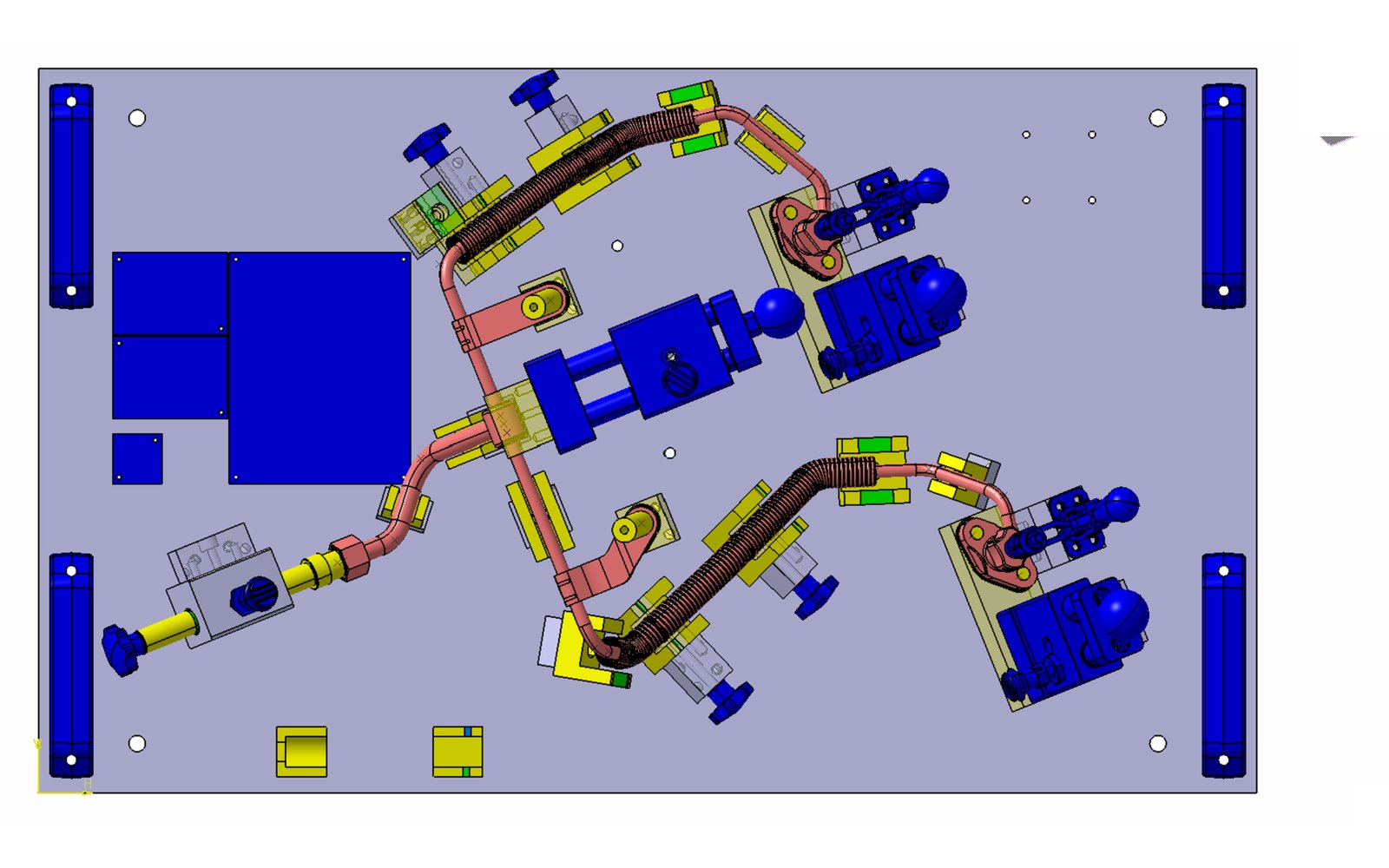
Bending and assembly jig for a hose assembly with tube elbow: positioning, joining and checking on one jig.
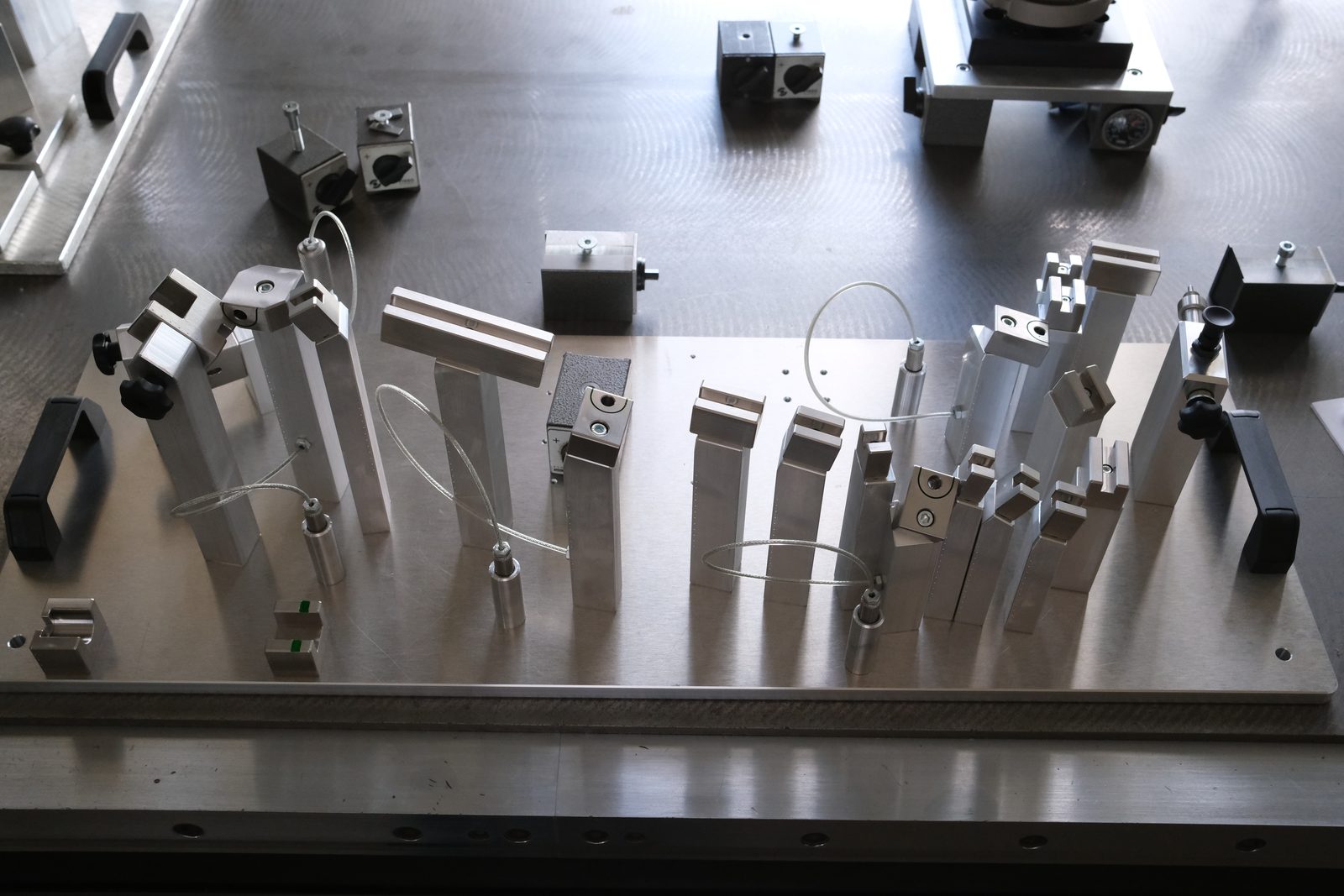
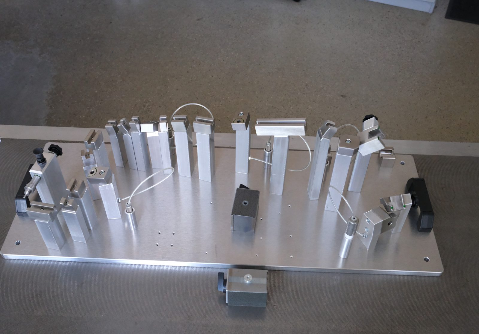
Finished checking fixture: stops, check pins with lanyards, toggle clamps.
From inquiry to ready-to-use gauge
The path from the first inquiry to the delivered gauge follows a fixed process. At every stage you know which step comes next and what information we need from you.
Inquiry and documentation
You send us a drawing, a STEP or IGES file or a sample part. If no documentation exists, we capture the geometry directly from the part and create the CAD model from it.
Technical review
Together we define which features the gauge has to check, which tolerances apply, where the datums are and how the part is loaded. This review determines how meaningful the inspection will be later on.
Design
Gauge body, locators, stops and clamping elements are designed in CAD, taking into account handling, operator access, wear behavior and later re-adjustment. Gauge design is also available as a stand-alone service without manufacturing.
Machining and assembly
Machining is done on 3-axis and 5-axis machining centers. The gauge is then assembled into a ready-to-use unit.
Final check and release
Before shipping, the gauge is function-tested with the part. An inspection report with a nominal-vs-actual comparison of the relevant features is available on request.
Delivery and support
You receive the gauge ready to use, including documentation. In case of wear, part changes or new variants, we take care of rework, modification and remakes.
What a gauge is made of
A gauge is an assembly of elements with different functions. Material selection depends on whether a component is a datum plane, a contact point or a handling element.
| Element | Typical material | Function |
|---|---|---|
| Base plate | Aluminum AlZnMgCu (7075), steel S235JR / S355J2 | Carries all locators and defines the datum plane of the entire gauge |
| Stops and datum pins | Tool steel 1.2379 (D2), 1.2842 (O2) | Wear-resistant contact points that unambiguously define the part position |
| Locators and V-blocks | Aluminum, steel, POM (acetal) | Locate the part repeatably and protect sensitive surfaces |
| Check contours | Steel | Embody the nominal geometry and allow a direct shape comparison |
| Guide bushings | Steel, bronze | Repeatable guidance of check pins and moving elements |
| Clamping elements | Standard components, steel | Hold the part during inspection without deforming it |
| Interchangeable plates | Aluminum, steel | Allow variant changes on the same base gauge |
We select the specific materials for your application during the technical review.
Where our gauges are used
Gauges are used wherever parts are manufactured in series and their geometry has to be assessed quickly and reliably. The following areas make up the majority of our orders.
Fluid line systems
Checking tube assemblies, hose assemblies and line sets for 3D shape, connector position and bend angle. Bend gauges are the most common inspection tool here, because the geometry is three-dimensional and hard to capture with standard measuring instruments.
Tube bending
Checking bent tubes and profiles directly after bending. The gauge immediately reveals springback, angular deviation and rotation and allows the bending parameters to be corrected while the process is running.
Sheet metal and forming
Verifying contours, cutouts and bends on sheet metal parts. Checking fixtures and contour gauges detect form deviations caused by tool wear or varying material properties.
Welded and brazed assemblies
Brazing fixtures hold individual components in their nominal position during joining and limit thermal distortion. After joining, checking fixtures verify that the assembly meets the required positional relationships.
Series assembly and final inspection
Used on assembly lines and in final inspection, wherever a fast go/no-go decision is required. The gauge makes the check operator-independent and requires no metrology skills.
Maintenance and replacement
Remaking worn, damaged or lost gauges, even if no drawing exists anymore. The geometry is captured from the existing gauge or from the part – see Reverse Engineering.
Gauge or fixture: what is the difference?
The two terms are often mixed up in tooling, but they describe different tasks. The distinction matters in practice because it determines the requirements for accuracy, materials and documentation.
A gauge checks
A gauge embodies the nominal geometry of a part and is used for comparison. It answers the question of whether a manufactured part is within the permissible deviation. Because the result depends on the gauge's own accuracy, a gauge is toleranced more tightly than the part it checks, and its dimensional accuracy is documented.
A fixture holds
A fixture positions and holds a part during an operation such as welding, joining, straightening or machining. The priorities are rigidity, access and handling. It makes no statement about the quality of the part; it enables the part to be processed repeatably.
In practice, hybrids exist: a welding fixture can include integrated check features, and a checking fixture can double as an assembly aid. We clarify which design makes sense for your application before design work begins. Read more on our page Jigs & Fixtures.
Questions about gauges and checking fixtures
What is a checking fixture?
A checking fixture (also called an inspection gauge or check fixture) is a dedicated tool that physically embodies the nominal geometry of a part. The manufactured part is loaded into the fixture, and deviations in hole spacing, contour or positional references become visible immediately. Unlike an individual measurement, the result is not a list of numbers but an immediate go/no-go decision. That makes the check fast and independent of the inspector's experience.
What is the difference between a gauge and a fixture?
A gauge checks, a fixture holds. The gauge compares actual and nominal geometry and is therefore toleranced more tightly than the part itself. The fixture positions a part during an operation such as welding, straightening or machining and makes no statement about quality. Hybrids are possible and common in practice.
What do you need from me for a quote?
A part drawing as PDF or a CAD file in STEP or IGES format is enough to get started. It also helps to know which features are to be checked and the production volume of the part. If no documentation exists, we capture the geometry from the existing part or an existing gauge with our portable measuring arm.
How long does it take to build a gauge?
Lead time depends on complexity, part size and the depth of manufacturing. Simple checking fixtures are often available within one to two weeks; extensive gauge systems with several locators take correspondingly longer. In urgent cases – for example when a gauge fails during running production – we prioritize the order and agree on a firm delivery date.
Can worn or lost gauges be remade?
Yes. A remake is possible even without an existing drawing. The geometry is captured from the existing gauge or the reference part with our portable measuring arm and turned into a CAD model. On that basis we build the gauge anew and can improve wear-prone areas in the design at the same time, so the new gauge lasts longer.
Do I receive a quality certificate for the gauge?
On request you receive an inspection report documenting the nominal-vs-actual comparison of the relevant features. It lists the part number, drawing revision, nominal dimension, tolerance, actual value and result. The report serves as evidence for your quality management and simplifies the release of the gauge.
Do you also build single gauges and small batches?
Yes. There is no minimum quantity. Most of our gauge orders are one-offs, since every gauge is tailored to a specific part. We also build sets of identical gauges when several inspection stations or plants need to be equipped.
Checking fixture or CMM fixture: which is right for my part?
A checking fixture gives an immediate pass/fail result right on the line, with no metrology skills required. A CMM fixture holds the part repeatably on the coordinate measuring machine or under the measuring arm and delivers measured values. For ongoing production inspection the checking fixture is faster; for initial sample inspection, process analysis and documentation the CMM fixture is the better choice. Many parts need both. We build both on the same datum system.
Do you also make standard gauges such as thread plug gauges or ring gauges?
No. CAD-IS builds part-specific custom gauges to drawing or CAD data. Standard catalog gauges such as thread plug gauges, limit plug gauges or setting rings are available at lower cost from specialized manufacturers.
Can existing gauges be repaired or modified?
Yes. We replace worn stops and check pins and re-adjust the gauge. If the part has changed, we modify the gauge design – for example to add an additional check feature. This also applies to gauges not originally built by us.
Gauge inquiry
Email us your drawing or CAD file and we will get back to you with a quote within 24 to 48 hours.